
Introduction
Deploy - Automated Generation Projects
This extension import wizard can be used for the automatic generation of Alarm Items, Historian tables and the Points table of a project. To do this, it is necessary to previously create Templates, Channels, and Nodes that are necessary for the project.
Categories should also be created to indicate how templates and Points should be used. The wizard, when it is executed, does the "blast", i. is, populates the tables mentioned with the records adapted to the specifications made.
Each client or user may have databases with default prototypes appropriate to their needs and culture. To create these bases you must:
n Define Templates for all bays using the naming and alarms rule of the user installation;
n Define the alarm and event generation behavior and choose the Alarm Groups that will be used in the project;
n Define the tables for the Historian, i.e Historian Tables.
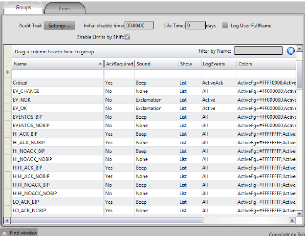
The Deploy Automatic Database Generation extension already defines a set of prototypes for group alarms. From these names one should choose those that meet the requirements of the customers. Probably, of the names below, each customer will use about a dozen.
The Group Alarms already available are listed below. The identification of each AlarmGroup is relatively intuitive as to its functionality. When running Deploy a first time, these groups are created and if there is doubt about the functionality, one can better understand looking at the complete set of fields of the record.
Use condition Change
EVENTOS_BIP
EVENTOS_NOBIP
Use condition HI
HI_ACK_BIP
HI_ACK_NOBIP
HI_NOACK_BIP
HI_NOACK_NOBIP
Use condition HIHI
HIHI_ACK_BIP
HIHI_ACK_NOBIP
HIHI_NOACK_BIP
HIHI_NOACK_NOBIP
Use condition LO
LO_ACK_BIP
LO_ACK_NOBIP
LO_NOACK_BIP
LO_NOACK_NOBIP
Use condition LOLO
LOLO_ACK_BIP
LOLO_ACK_NOBIP
LOLO_NOACK_BIP
LOLO_NOACK_NOBIP
Use condition Equal ou NotEqual
ACK_BIP
ACK_NOBIP
NOACK_BIP
NOACK_NOBIP
NOMSG_BIP
NOMSG_NOBIP
n Observation: To choose conditions Equal or NotEqual define together Limit with state in comments.
For each alarm group actually used in the Application, a corresponding category with the prefix ALARMGROUP_ followed by the alarm group name must be created.
Example: ALARMGROUP_NOMSG_NOBIP
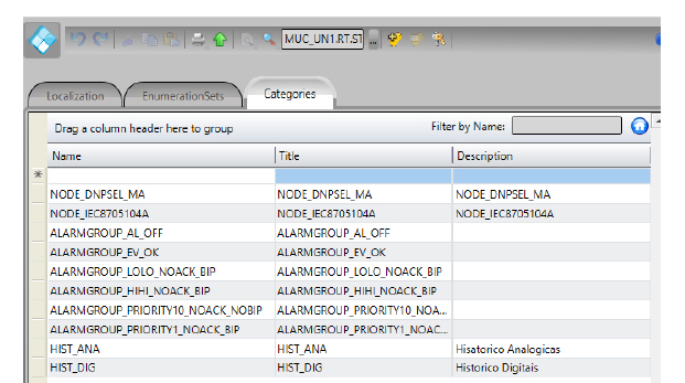
See the figure above (Run> Dictionaries) for the categories created for Alarm Groups and also for Nodes (in Devices) and for the Historian tables.
In order to create the Alarm items records for each tag, it will be enough to choose this category in tag record.
The application of a category to an object is used in an inherited way: that is, if it is applied to a hierarchically higher object, for example in a TRAFO template, all tags defined in this template will also have the same category. The categories assigned directly in the tags (leafs) are also cumulatively considered. In other words, the tag (lower-level object, or leaf) has all the categories (an OR of them) assigned to the top-level objects.
The user must manually create the channels and nodes of the Application according to the characteristics of the protocols used in the application. This parametrization must be done according to the IEDs with which the project will communicate.
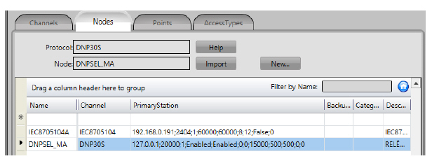
For each existing node, for which you want to automate the generation of records in the POINTS table, the user must define a category with the prefix NODE_ followed by the name of the node. For example, for the nodes defined in the figures below (Edit> Devices) the categories must be created:
n NODE_IEC8705104A and
n NODE_DNPSEL_MA
These categories should be assigned to all point tags that are handled by these communication nodes.
Typically, when you have templates that define higher-level objects, such as a Feeder, or a Trafo, where all the points monitored and controlled come through a single communication node, assigning the node category to these objects makes it much easier the task.
The user must create Categories for all the historian tables necessary for the application. For example, you can reference three historians as follows:
n H1M - Save records every minute;
n H5M - Save logs every five minutes;
n HVA - Saves records whenever the variable has its value changed;
For each referenced historian, you must create a corresponding category with the prefix HIST_ followed by the name of the historian table. In the case HIST_H1M, HIST_H5M and HIST_HVA.
You can create as many historians as you need, without naming restrictions, and with any save parameters, but there must necessarily be a category HIST_ + name of the historian table.
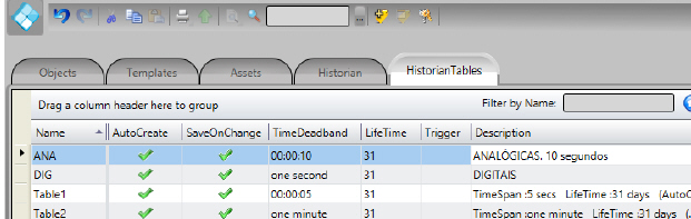
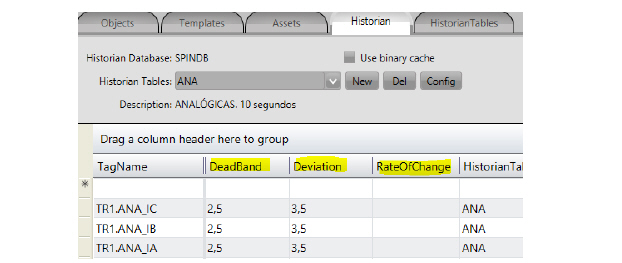
In the figure below (EDIT> TAGS) the ANA and DIG tables were created. The categories to be created by the user should be: HIST_ANA and HIST_DIG.
If prefer, the user only makes the reference and the tables will be automatically created by the Deploy application.
For each of the tags that you want to have their values and states recorded in each of these history tables, the corresponding categories must be applied.
Again here, remember that the work will be simplified if it is possible to apply the categories to higher-level objects. This facility will be directly derived from the way in which the templates are structured in the modeling of real objects.

To ensure better performance in maintaining and searching historical tables it is advisable to keep them with something around 100 tags in each. So, automatically Deploy when creating the tables uses the assigned name, plus numeral 01, 02, ... onwards, and creates as many tables as necessary to accommodate 100 tags per table. After creating the table the user must make the parameter adjustments of the tables according to their need.
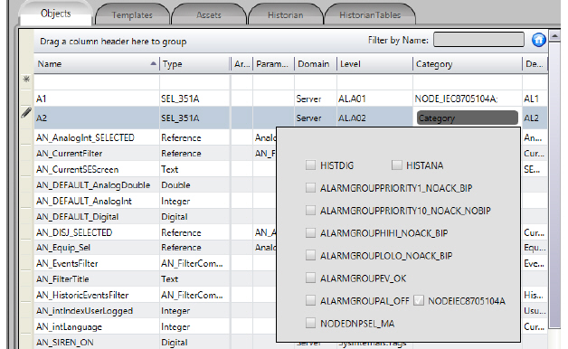
Veja na figura abaixo como impor uma categoria à um objeto. Clica-se na coluna categorias em (Edit>Tags>Objetos), e aparece a lista das categorias existentes. Pode-se escolher uma ou várias para um mesmo objeto, clicando nas caixinhas à esquerda de cada categoria. Na coluna categorias, fica o texto com o conjunto de nomes de categorias escolhidas, separadas por ponto e virgula (;).
In the default project, as presented above, already exist created: Alarm Groups, Templates, Channel, Nodes, Historians Tables, Dictionaries (Localization, Enumeration and Categories) and Symbol Library associated with user culture.
In order for the records to be created in the tables during deploying process, the tags in the objects and templates tables should be assigned to appropriate categories.
After making the assignments of categories, the creation of the records in the tables is guaranteed, but the records will be created with some important fields left blank to be filled later.
An additional facility available in the Deploy application is the ability to previously specify the contents for the most used and important attributes of these records. This is done by using the comments column, available in the tables of objects and templates. In these columns, for each tag, it is possible to specify by means of text with key words the contents to be used in the generation of the records. See Additional Attributes for details on this procedure.
The desired pre-defined categories should be assigned to the tags (leafs) in the various templates, as shown below. Note that categories imposed on higher-level objects, defined with User Types (Templates), are inherited by the lower levels in the instantiated objects.
See in the figure below how to impose a category on an object. Click the categories column in (Edit> Tags> Objects), and the list of existing categories appears. You can choose one or several for the same object by clicking on the boxes to the left of each category. In the Categories column, the text with the set of selected category names is separated by a semicolon (;).
See the following examples:
1. In the figure above, the category NODE_IEC8705104A defines the communication node with the relay for object A1 (type SEL_351A). In this template (type) all the measurement and status tags that are to be read in this IED are defined.
2. If the leaf (tag) AMP in a template BAY, need to create a LO type Alarm Item that requires recognition and issue beep, this tag should be associated with ALARMGROUP_LO_ACK_BIP category;
3. If for the same tag if you want your values to be saved in the history in table H2, you must also have the category HIST_H2;
4. If this tag has an address in the field and belongs to a node named DNP1, it must also have the category NODE_DNP1
5. Each of the categories of different types assigned will be used by the Base Automatic Generation application, for the selection of tags that will be used in the creation of corresponding records in the respective tables.
In order for the tags to be created automatically, they must necessarily be assigned a Level (assets), and they must have the Domain attribute as server. These attributes can be directly in the tag or in any object of a higher hierarchical level, so that the leaves inherit these attributes.
Once all the templates have been created, the categorizations of the tags of each template are made, and the desired comments fields are filled in, the next step is to create an object to instantiate the desired template.
Example: To create a trafo 1 from a template named TRAFO:
1. Go to Edit> Tags> Objects and create an object
Name = T1
Type = TRAFO
Level must also be completed.
2. If it is considered appropriate, you can still assign other categories and define comments to these higher level objects. At these higher levels it is convenient to assign categories of the type of communication Nodes.
For the specification of previously defined contents, to be used in the important attributes in the records to be created in the tables by Deploy, is available the ease of using the comment fields in the tables objects and templates.
For each attribute considered, in each of the tables, key words were created, which are mostly the names of the columns themselves. In each tag, or top level object, you can type in the comments column, texts formed with these key words and the contents that you want. The Deploy application will use these contents in generating the related records in the Alarm Items, Points, and Historian tables.
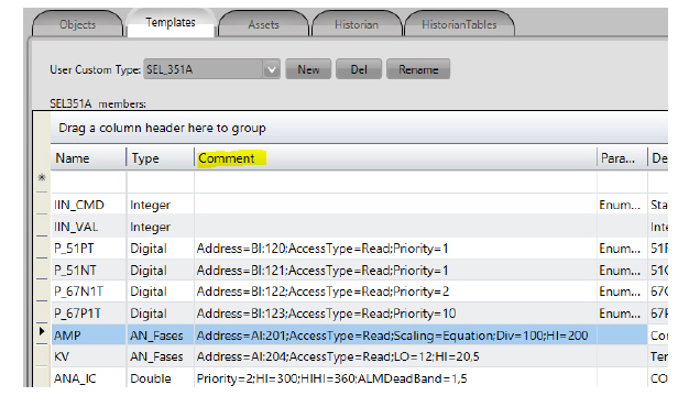
The figure below shows the use of the comments column in a template. The following items present the attributes (columns) considered, the key words for each table, and a brief description of the usage.
The following table shows the key words of columns used.
|
Keyword |
Column |
Contents |
|---|---|---|
|
LO
|
LIMIT |
Float number, to be used in registers whose alarm group refers to condition Lo (lower operational) |
|
LOLO |
LIMIT |
Float number, to be used in records whose alarm group refers to LoLo (lower emergency) condition |
|
HI |
LIMIT |
Float number, to be used in registers whose alarm group refers to Hi condition (upper operational) |
|
HIHI |
LIMIT |
Float number, to be used in records whose alarm group refers to HiHi condition (upper emergency) |
|
EQUAL |
LIMIT |
Integer representative of the state in which the alarm is active |
|
NOTEQUAL |
LIMIT |
Integer representative of the state in which the alarm is NOT active |
|
PRIORITY |
PRIORITY |
An integer number from 1 to 10 to be used as an alarm priority for the item |
|
ALMDEADBAND |
DEADBAND |
A real number to be used as dead band in the generation and alarm normalization
|
|
ALARMAREA
|
Area |
Name of a Alarm AREA, this alarm item will belong to. |
Example:
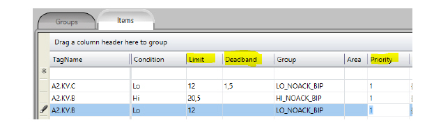
1. In the comment field of tag A2.KV.C would have been placed
Priority = 1; LO = 12; Alm_DeadBand = 1.5
2. In the comment field of tag A2.KV.B. would have been placed
Priority = 1; HI = 20.5; LO = 12
3. See in the figure below the columns filled with these key words:
When a tag or object is defined by multiple levels of templates, the comment that will be processed by Deploy will be formed by concatenating all the comments specified in the forward hierarchy. In the case of more than one specification with the same keyword, the one that will actually be used is the one that is defined at the lowest level of the route
The following table shows the key words of columns used.
|
Keyword |
Column |
Contents |
|---|---|---|
|
ACCESSTYPE |
AccesType |
Identification of the AccessType to be used. Content is case sensitive: use case correctly.
|
|
ADDRESS |
Address |
Text with the correct content for the protocol used. Example for a digital point in DNP30 with address 328 the text should be: BI: 328
|
|
DATATYPE |
DataType |
Text with the correct definition content of a Data type: eg DWord or Long |
|
MODIFIERS |
Modifiers |
Can be specified for protocols that accept them, such as Bit, ByteSwape, WordSwap, DWordSwap, etc. For example: ByteSwap = True; WordSwap = True
|
|
SCALING |
Scaling |
The type of Scaling used: Linear, Equation, TagMinMax, TagScaleMinMax |
|
Div |
Scaling |
For the case of scaling Equation, sets the value of the divider (float) and this text must follow the type of Scaling
|
|
Add |
Scaling |
For the Scaling Equation case, define the value to be added (real)
|
|
EngValue1 |
Scaling |
For the case of Linear Scaling Float value should follow the type of Scaling
|
|
EngValue2 |
Scaling |
For the case of Linear Scaling. Float value should follow the type of Scaling
|
|
DeviceValue1 |
Scaling |
Scaling For the case of Linear Scaling. Float value should follow the type of Scaling
|
|
DeviceValue2 |
Scaling |
Scaling For the case of Linear Scaling. Float value should follow the type of Scaling
|
|
TagMin |
Scaling |
For the Scaling TagMin case. Float value should follow the type of scaling
|
|
TagMax |
Scaling |
For the Scaling TagMax case. Float value should follow the type of scaling
|
|
TagScaleMin |
Scaling |
For the Scaling TagScaleMin case. Float value should follow the type of scaling
|
|
TagScaleMax |
Scaling |
For the Scaling TagScaleMax case. Float value should follow the type of scaling
|
|
DeviceMin |
Scaling |
For the Scaling cases TagMinMax and TagScaleMinMax, they represent the minimum values received from the field |
|
DeviceMax |
Scaling |
For the Scaling cases TagMinMax and TagScaleMinMax, they represent the maximum values received from the field |
|
NodePrefix |
Node |
When you have a template of an object, for example, the points of a feeder, and each instance of the object will use a different Node for communication, one category can be used as a single name, and prefix this name for each instance. Of course, all nodes so referenced must exist previously in the project. |
|
AddressPrefix |
Address |
In protocols such as IEC-61850 and OPC, addresses are repeated for different IEDs owith same settings. Templates can refer to these addresses, but in the final on Points table, these addresses need to be prefixed with the name assigned to the IED, (first level) of the reference. This prefix can be defined here at the instantiated object level. |
Examples:
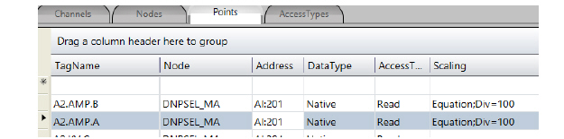
1. In the comment field of the A2.AMP object (which has a Phases subtype) would have been placed
ADDRESS = A1: 201; ACCESSTYPE = Read; SCALING = Equation; Div = 100
2. In the following example we used the Address and Node Name Prefixes in objects that instantiate templates. See the comment field, see that if you need some tab like the underscore or the point, they should be specified in the comment.
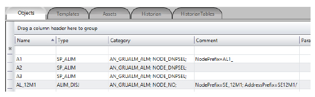
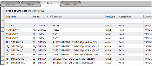
3. See how it was after the generation in POINTS. (AddressPrefix). In the case of IEC61850, the name of the Logical Device would be SE12M1.
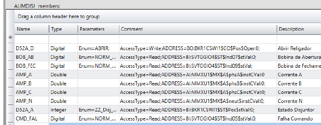
4. In this Template ALIM_DISJ we had tags for reading by protocol IEC 61850. The addresses placed in the tags were without the Logical device, which was used with the NodePrefix.
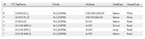
5. And then the Points with nodes prefixing (NodePrefix): :
The following table shows the key words of columns used.
|
Keyword |
Column |
Contents |
|---|---|---|
|
DEVIATION |
Deviation |
Deviation value (float) compared to previous for new recording |
|
HISTDEADBAND |
DeadBand |
DeadBand value (float), Dead band compared to previous value |
|
RATEOFCHANGE |
RateOfChange |
Maximum rate of change from previous value for new recording. real. |
Example
1. In the comment field of object TR1 it would have been placed
HIST_DEADBAND = 2.5; DEVIATION = 3.5
To automatically generate the project (blast), you must run the Deploy extension that will search for all objects that have not been created and create them.
Go to Run> Extensions
1. Choose the Deploy symbol;
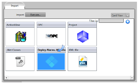
2. When you call this extension, a window appears to follow up the execution.
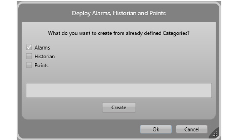
3. Choose what tasks you want to be performed. Mark one or all options.
4. Click the Create button, and follow the creation of each of the tables and their records being executed.The progress will be shown on box inside dialog.
Verifying whether or not the object has already been created is done automatically by Deploy, which checks to see if an element with the same name already exists and, if positive, does not recreate it a second time.
The records for the following tables will be created:
n Tags / Historian
n Device / Points
n Alarm / Items
Comments:
1. In devices / points all the inputs and outputs associated with the nodes are created. You must complete the table with addresses and AccessTypes, if necessary. Export from Action.NET to a worksheet, copy the addresses from an Excel spreadsheet of correct addresses, and import it back into Action.NET.
2. In the Alarms table and in the definition of the templates the names and acronyms are very important because they are part of the culture of the client. Limits for HI, LO, HIHI, and LOLO alarms must be entered manually.
3. If for some reason you wish to re-create the Historian table, you must remove all the items already created.
